The Carrier, Churchill, 3-inch Gun Mk I
by Mark W. Tonner
The war diary of 1st Canadian Army Tank Brigade Heavy Support Company for June 1942 described the Carrier, Churchill, 3-inch Gun Mk I as, “…a temporary expedient to deal with super heavy enemy tanks, should such be used until the 17-pounder anti-tank gun is issued.” This Churchill variant more or less came into being because the British needed to find a weapon that would be powerful enough to defeat German tanks in the event of an invasion. As an expedient measure, it was a quick and effective means of transporting the heaviest possible anti-tank gun on some sort of tank chassis. The British chose the 3-inch, 20-hundredweight anti-aircraft gun to fulfil this role, opting to install it in a limited traverse mount on the chassis of the Churchill Mk III tank. The idea of mounting the 3-inch anti-aircraft gun on a tank chassis for use in the anti-tank role, was first raised in March 1941 at a meeting of the British Director General of Tanks and Transport committee. Then, the committee was advised that the British Defence Committee had requested that the 3-inch anti-aircraft gun should be carried in some tanks, as a temporary measure until sufficient stocks of the 6-pounder anti-tank gun became available. By 1940, the 3-inch, 20-hundredweight anti-aircraft gun was being replaced in the British Army by the new 3.7-inch anti-aircraft gun, so a ready stock of the 3-inch anti-aircraft guns were available.

The initial contract card for Contract No. T.2787, dated 25 July 1941, for 100 (later amended to 50) Tanks, A22, “Special Type” (Carrier, Churchill, 3-inch Gun, Mk I), that was placed with Vauxhall Motors Ltd. Also recorded on the card, is the block of Census Numbers assigned , S31273 – S31321, along with the completion date of 2 November 1942. Source: author’s collection.
Within two weeks of the Director General of Tanks and Transport committee meeting, the British War Cabinet approved mounting the 3-inch anti-aircraft gun on a tank chassis, followed a week later by the Director General of Tanks and Transport informing the Defence Committee that the Churchill chassis was the best choice. Vauxhall Motors Ltd., of Luton, Bedfordshire, were asked to design the vehicle and, by the end of April 1941, had more or less completed the general arrangement drawings. Early in July 1941, Vauxhall had completed a wooden mock-up and the Department of Tank Design issued them a contract (Contract No. T.2787) for 100 Tanks, A22, “Special Type” (Carrier, Churchill, 3-inch Gun, Mk I) on 25 July. Having completed the pilot model, Vauxhall sub-contracted (Contract No. T.11614) out the assembly to Beyer, Peacock & Company, Ltd., of Manchester. In December 1941, the Director General of Tank Supply reduced the order to 24 vehicles, but subsequently increased this to 49 in January 1942. Production began in May 1942 but, with the threat of invasion fading away, the average output was one per week. The contract was completed on 2 November 1942, and the tanks were assigned the Census Numbers S31273 – S31321.

The contract card for Contract No. T.11614, under which Vauxhall sub-contracted out the assembly to Beyer, Peacock & Company, Ltd of Manchester, for 49 Tanks, A22, “Special Type” (Carrier, Churchill, 3-inch Gun, Mk I), with reference to the initial Contract No. T.2787, again showing the block of Census Numbers assigned , S31273 – S31321, along with the completion date of 2 November 1942. Source: author’s collection.
In appearance, the Carrier, Churchill, 3-inch Gun Mk I resembled a standard Churchill Mk III tank, but without the turret. Instead, it had a large fixed box-type superstructure which housed the main fighting compartment, with the gun mounted low down at the front, to the left of the driver’s position. Each vertical side plate of the superstructure had a circular pistol port. This port was hingeless and had a rapid opening and closing control. Access was either through the hinged door fitted in the rear vertical plate, or through a hinged double door hatch fitted in the roof, which also acted as the commander’s cupola, which was rotatable and was equipped with two periscopes. Each side plate had a large stowage bin, one mounted forward on the left and the other mounted to the rear on the right. A No. 33 sighting telescope was located in a fabricated bracket, in an open aperture in the left upper corner of the front plate, in a position convenient to the gun layer, directly above the driver’s visor. The hull sides retained the square escape doors, as on the Churchill Mk III, the tracks were fully covered and the engine air intake louvres (on the hull sides) had the opening on top.
A No. 19 wireless (radio) set was housed in the main fighting compartment. This set included an “A” set for general use, a “B” set for short range inter-tank work at troop level, and an intercommunication unit for the crew, so arranged that each member could establish contact with any one of the others. Adequate provision was made for the stowage of both ammunition and equipment, both within the interior and on the exterior of the vehicle. A comprehensive tool kit was provided with the vehicle so that every operation listed in the routine maintenance section of the Carrier, Churchill, 3-inch Gun Mk I Service Instruction Book (August 1942) could be efficiently carried out.

An image of the Carrier, Churchill, 3-inch Gun Mk I, showing the front of the large fixed box-type superstructure, that replaced the turret. Note the open aperture in the left upper corner of the front plate directly above the driver’s aperture, for the No. 33 sighting telescope and the location of the 3-inch, 20-hundredweight high velocity anti-aircraft gun, in the front plate. Also visible, on the turret roof to the right of the open aperture for the No. 33 sighting telescope, is the external triple-vane sight that was provided for the crew commander, so that he could bring the driver into rough alignment with the target. Source: author’s collection.
The commander’s position was located midway along the right side of the superstructure, inside the roof hatch. Directly in front of the commander was the gun layer’s position with the loader on his left. The driver was located in front of the gun layer, in the normal driver’s location for a Churchill tank. Since the 3-inch 20-hundredweight gun was mounted in a fixed turret, it could only be used with open sights. The commander was also provided with an external triple sighting vane, the outside vanes of which were painted white and corresponded to the free 5-degrees in either direction of the gun, so that he could bring the driver into line with the target. If a target appeared anywhere within this vane, when sighted through the commander’s periscope, the gun was then able to be layed on that target by its own traverse and without movement of the vehicle, provided, that the gun was at its central traverse point at the outset. Because the mounting had only 5-degrees of traverse, either side of the centre line, the driver had to be in place, with engine running, in order that he could traverse the Carrier into rough alignment with the target. To assist him in knowing when the gun was reaching the limit of its traverse, he had a traverse indicator alongside his visor. The gun could only be fired while the vehicle was stationary. Because of its heavy weight, the gun had to be locked at full elevation when the Carrier was travelling to prevent damage to the gun.
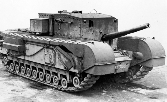
In this right side view, it can be seen, that in appearance, the Carrier, Churchill, 3-inch Gun Mk I resembled a standard Churchill Mk III tank, but without the turret. Note the large fixed box-type superstructure, which housed the main fighting compartment, with the gun mounted low down at the front to the left of the driver’s position. As can be seen, the hull sides retained the square escape doors (with circular pistol port) of the Churchill Mk III, the tracks were fully covered, and the engine air intake louvres (on the hull sides) had the opening on top. The anti-aircraft mounting for the .303-inch Bren (Mk I) machine gun, can be seen stowed just above the circular pistol port in the vertical side plate of the superstructure. Also, of note, in this photo, the 3-inch gun, is at full elevation, the position it would be locked in when the Carrier was travelling, in order to prevent damage to the gun. Source: author’s collection.
During an engagement, the commander used his external sighting vane to direct the driver to bring the Carrier into rough line with the target. The gun layer then used his limited traverse to lay the gun on the target. Once laid on the target, the gun was fired using a strap with one end connected to the trigger release mechanism, and the rest of the strap forming a harness for the gun layer, who fired the gun by a body movement. The gun layer was provided with two hand wheels, one to elevate the gun, and the other to traverse the gun. Loading and unloading was carried out by hand. A round of armoured precising ammunition weighed 12½ lbs. When firing, the instruction book stated that the rear door had to be open and the engine held at 1,500 revolutions per minute to provide adequate ventilation for the crew. However, it was found during trials that by redesigning the two electric fans situated at the rear of the fighting compartment to extract air at 900 cubic feet per minute, firing could be carried out with the Carrier completely closed down.

In this view of S31273R, details of the left side of the Carrier, Churchill, 3-inch Gun Mk I, can be seen. The external triple-vane sight, which was provided for the crew commander, is clearly visible on the turret roof. Source: author’s collection.
On 8 April 1942, Headquarters 1st Canadian Army Tank Brigade received a letter indicating that General Headquarters, Home Forces had recommended to the War Office that several army tank brigades, including 1st Canadian Army Tank Brigade, each be issued with nine of the Carrier, Churchill, 3-inch Gun, Mk I. Each brigade would form three troops of three Carriers each, with one troop being attached to each army tank battalion. No additional personnel were authorized and the Carrier would be carried as extra to the war establishment of each army tank battalion. On 23 April, Headquarters, 1st Canadian Corps confirmed to 1st Canadian Army Tank Brigade, that they would receive nine Carriers as a temporary expedient to deal with super heavy enemy tanks until the 17-pounder anti-tank gun was issued. The brigade commander (Brigadier R.A. Wyman) 1st Canadian Army Tank Brigade was asked for his comments on the manning and distribution of the Carriers in his brigade.

In this external stowage sketch, the circular pistol port, in both the square escape door, and the vertical side plate of the superstructure, can be seen, along with the hinged door fitted in the rear vertical plate, and the hinged double door hatch fitted in the roof, which acted as the commander’s cupola, forward of which is located the external triple-vane sight that was provided for the crew commander. Note the external auxiliary fuel tank, on the rear plate, which carried an additional 32.5 gallons of fuel. This auxiliary tank was connected to the main fuel system, but could be jettisoned from the tank in an emergency. Source: author’s collection.
Brigadier Wyman replied on 29 April 1942, proposing a distribution of three Carriers per battalion, as a heavy anti-tank troop. He also suggested that these carriers be manned by the personnel from the “Special Increment” of four officers and seventy-seven other ranks authorized for each tank battalion. This “Special Increment”for each tank battalion, which was authorized under Canadian Military Headquarters Administration Order No. 68, dated 5 April 1942, was a fixed scale addition of personnel held by No. 2 Canadian Armoured Corps Reinforcement Unit, to the authorized War Establishment strength for each of the tank battalions of 1st Canadian Army Tank Brigade. On 19 May, Headquarters, 1st Canadian Corps directed that the Special Increment would not be used to man these carriers, but that an ad-hoc unit would be formed. This would be known as the 1st Canadian Army Tank Brigade Heavy Support Company, and Brigadier Wyman was to submit a proposed war establishment at once. This was submitted to the corps headquarters on 22 May. In it, Brigadier Wyman proposed to establish a company headquarters capable of administering three self-contained troops, in much the same manner as an anti-tank regiment headquarters functioned in an infantry division. Each troop would have three Carriers and could be assigned to an army tank battalion. The proposed personnel strength of the Company was ninety-seven all ranks, twenty-eight in company headquarters, and twenty-three in each of the three troops.
This was formalized in Canadian Military Headquarters Administration Order No. 167, with effect from 24 June 1942, under the authority of National Defence Headquarters Cable GSD 602. This granted approval for the formation of the 1st Canadian Army Tank Brigade Heavy Support Company, under the command of Headquarters, 1st Canadian Army Tank Brigade, on a field return basis, from field and reinforcement personnel. The war establishment for “A Canadian Army Tank Brigade Heavy Support Company” was also authorized under the authority of GSD 602, with effect from 24 June 1942. The war establishment, as authorized, was exactly the same as the proposed one that Brigadier Wyman had submitted to Headquarters, 1st Canadian Corps on 22 May 1942.

An interior stowage sketch, looking forward from the rear of the fighting compartment. Note the location of the No. 19 wireless (radio) set, in the upper-left hand corner of the fighting compartment. Source: author’s collection.
On 30 June 1942, Headquarters, 1st Canadian Army Tank Brigade, ordered the three tank regiments (on 15 May 1942 the tank battalions of the brigade had been redesignated tank regiments) of the brigade to facilitate the rapid formation of the 1st Canadian Army Tank Brigade Heavy Support Company and to make it an efficient fighting unit as quickly as possible. To that end, it had been decided that all personnel would be drawn from the units of the brigade. By 3 July 1942, each regiment was to nominate one officer to be a troop commander and to supply the personnel for one complete troop as selected by the troop commander. Each regiment was also to submit recommendations for non-commissioned officers to fill the positions of squadron sergeant-major, squadron quartermaster sergeant, and squadron mechanist sergeant in the company headquarters of the new formation. On 1 July 1942, the brigade commander selected Captain G.S.G. Jones of The Three Rivers Regiment as the first officer commanding, with Captain D.C. Matthews of Headquarters, 1st Canadian Army Tank Brigade, as second-in-command of the heavy support company. Both of these officers were later succeeded upon posting away from the unit to other duties in the fall of 1942, by Major C.H. Humber and Captain J.D. Pearson, respectively.
Brigadier Wyman and Captain Jones met at Headquarters, 1st Canadian Army Tank Brigade on 15 July to discuss various subjects in relation to the formation and organization of the heavy support company, such as training, and vehicle allotment. The point of standardizing the unit cap badge was brought up and it was agreed that the Canadian Armoured Corps cap badge would be adopted for wear. It was also agreed that the vehicles of the 1st Canadian Army Tank Brigade Heavy Support Company, would adopt the Arm of Service marking of Headquarters, 1st Canadian Army Tank Brigade (serial 171) along with the 1st Canadian Army Tank Brigade formation sign of a Gold or Yellow Maple Leaf centred on an 8-inch wide by 10-inch high black background square, with a black left facing image of a Ram superimposed centrally on the maple leaf. Effective 31 October 1942, the formation sign of the 1st Canadian Army Tank Brigade was changed to a Gold or Yellow Maple Leaf superimposed centrally on an 8-inch wide by 10-inch high background square of three equally horizontally divided strips of black-over-red-over-black.

An interior stowage sketch, looking to the rear of the fighting compartment. Note the stowage for the 16 high explosive rounds, in the two bins which were painted red, and the stowage of armour piercing rounds, on the left and right, and the loader’s seat, in front of the left-hand high explosive round been. Source: author’s collection.
The headquarters of the 1st Canadian Army Tank Brigade Heavy Support Company was established at Warninglid, Haywards Heath, Sussex, being co-located with that of 1st Canadian Army Tank Brigade Headquarters Squadron. During the rest of July, the new formation was organized and arrangements made for unit personnel to attend courses at various schools and training establishments. Also, a location was sought that could hold the new formation, and on 27 July, Ovingdean School, Ovingdean, Sussex, became the permanent accommodation for the 1st Canadian Army Tank Brigade Heavy Support Company. Starting in August 1942, the gunnery wing of the British Army Armoured Fighting Vehicle School at Lulworth Camp, Dorset, began to run a one-week course on the Carrier for unit personnel. Some were also sent to attend courses on the Carrier at the Driving & Maintenance Wing of the Armoured Fighting Vehicle School at Bovington Camp, Dorset. Unit fitters, driver-mechanics, motor-mechanics and storemen were sent off on courses at Royal Army Ordnance Corps schools at Bordon Camp, Hampshire and at Canterbury, Kent.
It was not until September 1942 that the Carrier began to be issued to the 1st Canadian Army Tank Brigade Heavy Support Company. By 19 September, they had been issued five equipments, all based on reworked Churchill Mk III tanks. One problem that the crews encountered with these Carriers, was that they had a tendency to throw their tracks when turning at speeds of 10 miles-per-hour or higher. In October 1942, the company was redesignated a squadron (1st Canadian Army Tank Brigade Heavy Support Squadron), so as to conform to Canadian Armoured Corps nomenclature. By 10 October, the squadron had been issued three more equipments, bringing their holdings up to a total of eight, and by 7 November the squadron held a total of ten (one surplus) (S31274R, S31275R, S31276R, S31277R, S31278R, S31279R, S31280R, S31281R, S31283R, and S31284R). The surplus Carrier remained with the unit until 23 January 1943, when one Carrier (S31277R), having been in workshop since 26 December 1942, was turned into No. 1 Sub-Depot of No. 1 Canadian Base Ordnance Depot, Bordon Camp, Hampshire.
On 15 February 1943, Headquarters, 1st Canadian Corps ordered that 1st Canadian Army Tank Brigade Heavy Support Squadron was to be broken up immediately. Headquarters, 1st Canadian Army Tank Brigade confirmed this on 21 February and by 4 March 1943, having returned all vehicles and stores, and with all personnel of the squadron having been dispersed, the squadron was disbanded.
Characteristics of the Carrier, Churchill 3-inch Gun Mk I
Crew: four (commander, gun layer, loader, driver)
- Weight: 39 tons
- Length: 26 feet 1 inch (including gun)
- Width: 10 feet 8 inches (with air intake louvres on sides)
- Height: 9 feet 1 inch
- Length of tracks on ground: 12 feet 8 inches
- Width over tracks: 9 feet 1 inch
- Clearance under hull: 1 foot 9 inches
- Armour thickness: Superstructure: frontal plate (basically an extension of the vertical driver’s visor plate) 89 millimetres
- Side plates: 76 millimetres
- Rear plate: 76 millimetres
- Roof plate: 15 millimetres
- Road speed: 15½ mph
- Cross country speed: 8 mph (approximately)
- Engine: 12 cylinder Vauxhall Bedford twin-six 350 horsepower
- Weight of engine: 3,376 lbs (dry)
- Fording depth: 3 feet 4 inches (without preparation)
- Trench crossing ability: 10 feet
- Vertical obstacle capacity: 2 feet 6 inches
- Turret: Fixed
- Main armament: 3-inch, 20-hundredweight – high velocity anti-aircraft gun
- Elevation main armament: minus 10-degrees to plus 15-degrees
- Traverse main armament: 5-degrees either side of the centre line
- Muzzle velocity main armament: 2000 feet per second (able to penetrate 100 millimetres of armour at 200 yards)
- Ammunition stowage: 49 rounds of armour piercing and 16 rounds of high explosive
Remarks: Each tank was also supplied with one .303-inch Bren (Mk I) machine gun with an anti-aircraft mounting and six 100-round drum type magazines, and two .45 calibre Thompson Sub-Machine Guns with thirty-two 20 box type magazines each, and six Grenades No. 36 Mk I
If you enjoyed this article please ‘rate’ it using the stars below. You may also leave a comment.

For more information on the Churchill tank and its use by the Canadian Army is available in the author’s book, published by Service Publications at www.servicepub.com.

In the book “Mr. Churchill’s Tank – The British Infantry Tank Mark IV” David Fletcher mentioned a plan to rearm Churchill Gun Carrier with 3.7″ gun (which was dropped). Do you have any details about that plan?
This is a great article, and timely for those of us in the modeling hobby as AFV club have now released a kit of this vehicle. I know it’s a long shot as they only served with the Canadian Armed forces for a very short time, have you been able to find any photos of them in Canadian service?